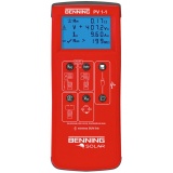
Photovoltaic Installation Tester BENNING PV 1-1
Advantages of the product
- Testing in compliance with VDE 0126-23 (DIN EN 62446)
- easy to use - selection of options with the use of buttons
- speed - short measurement time of a few seconds at most
- safety - the measurement can also be done on a photovoltaic system during the supply of energy
| BENNING PV 1-1 | |
| indication | graphic display |
| protective conductor resistance | 0.05 Ω – 199 Ω |
| testing current | ± 200 mADC |
| open circuit voltage | 5 V – 1000 VDC |
| short-circuit current | 0.5 A – 14.99 ADC |
| insulation resistance | 0.2 MΩ – 199 MΩ |
| testing voltage | 250 V, 500 V, 1000 VDC |
| load current | 0.1 A – 40 AAC/DC (by means of clamp) |
| measured value memory | 200 data record |
| interface | USB |
| scope of delivery | carrying case, measuring leads, crocodile clips, MC4 measuring leads , sunclix measuring leads, batteries, CD-ROM with download software, calibration certificate |
Features
- clear and unambiguous display of all measurement results
- safe measurement connection, even if the photovoltaic system is delivering energy
- automatyczne wyświetlanie napięcia polaryzacji, audio / wizualne ostrzeżenie przy odwrotnej polaryzacji
- kompensowanie rezystancji przewodów pomiarowych
- przesyłanie wyników pomiarów poprzez interfejs USB
- automatic display of voltage polarity with audio/ visual warning for reverse polarity
- null balance of the measuring leads
- measured values memory for 200 display indicatons for (automatic) string-string comparison incl. warning in the event of short circuit current and open circuit voltage deviations > 5 %, download of measuring results occurs by means of USB interface
- ISO measuring result with “pass / fail” information
- direct connection to all photovoltaic modules with MC4 or „Sunclix“ connectors
- LC display with background lighting
- automatic switch off after 60 seconds
- the testing can be based on photovoltaic modules or the complete photovoltaic system
Measuring functions
- protective earth conductor resistance measurement with test current of 200 mA
- open-circuit voltage measurement of the solar modules or PV strings up to 1,000 VDC
- short-circuit current measurement via an internal circuit up to 15 ADC without any danger for the user
- insulation resistance measurement between the active DC conductors (+ / -) and earth with adjustable testing voltage of 250 V, 500 V, 1,000 VDC)
- functional test via current measurement up to 40 A AC / DC (by means of current clamp adapter BENNING CC 3, item no. 044038)


Controls and displays:
- Digital display shows the test progress and the results of the individual measurements.
- RPE button, Testing the resistance of the protective conductor
- Auto Button, initiates automatic PV test procedure according to VDE 0126-23 (DIN EN 62446)
- NULL button, for resetting resistance of measuring line
- Button VISO, selection of test voltage for measurement of insulation resistance
- Call up the stored readings (display values)
- USB interface (micro-B slot), for connecting the USB connection cable
- Save the displayed measurement values (displayed values)
- + PV test socket (red), for connecting the red measuring cable to the PV plug connector
- - PV test socket (black), for connecting the black measuring cable to the PV plug connector
A - RPE Voltage polarity indicator shows the polarity of the DC voltage on the 4 mm K and L test sockets. AC voltage is displayed alternately "+" and "-".
C - NULL RPE (Null-Offset), appears at the compensation (zero correction) of the resistance of the measurement line.
D - (Warning: hot surface), with the symbol activated, immediately disconnect the BENNING PV 1-1 from the PV generator. Connect the BENNING PV 1-1 only after the symbol has expired.
E - polarity display), shows DC polarity on the test sockets PV 9 and 10 on.
F - (Caution, dangerous voltage) has been detected.
G - (RPE LOCK) (found), actively when continuous measurement is activated RPE.
H - (Caution), when the symbol is activated, follow the instructions in the operating instructions to avoid dangers.
I - RISO (good)/(bad), indicates whether the measured insulation resistance is within the set limits.
J -Selection of the test voltage of the insulation, indicates the test voltage of the measurement of the insulation resistance.
K -Error, Familiarize yourself with specific error codes (see section 9.1 Error codes for details).
L - STORE, LCD data is stored in the internal memory
M - RECALL, the stored LCD data has been loaded from the internal memory.
N - Memory display shows the current memory location (1 ... 200).
O - Voltage/ Current deviation indicates the deviation of the measured values of no-load voltage and short-circuit current greater or less than 5%.
P - Battery icon appears on discharged batteries
Opinions
ℹ️ Viewed reviews are moderated. We do not verify that they come from customers who have purchased the product.